


Product Description
The HDA3 is a modular stock/brace system developed from a collaboration between Haga Defense and A3 Industries. The HDA3 was designed specifically to integrate seamlessly across dozens of firearm platforms without sacrificing strength or aesthetics to do so.
The HDA3 fills a footprint that the gun industry has already come to love while providing a level of quality, modularity and durability that has never been offered in a similar package. The HDA3 is designed, manufactured and assembled in the USA.
FEATURES:
- Folding Steel Hinge: The HDA3 utilizes a steel hinge assembly, ensuring a strong lockup in the straight and folded position that will not degrade with use. The HDA3 will by default fold to the left side canted at 3.5 degrees. Right side folding variants will be available at a later date.
- Strong Bones: The HDA3 is designed with all metal internal components for maximum durability. An aluminum cheek riser button and length adjustment latch both interface with an extruded aluminum spine that ties into the steel hinge.
- Stock & Brace Configurations: The HDA3 is available as a stock with an injection molded extension and rubber buttpad or as a brace with an injection molded extension designed to accept a variety of arm braces. See below for brace compatibility.
- Adjustment: The HDA3's length can be adjusted in .5" increments between 7 positions. The cheek riser can be used in three positions. In the lowered position, raised .25" or raised .5". Both adjustments can easily be manipulated one-handed.
SPECIFICATIONS:
- Mounts directly to the KRISS Vector (Gen2)
- Will NOT fit Gen 1 or Gen 3
- Nylon Adapter
- Length:
- Stock configuration: 8.63-11.63"
- Brace configuration (without brace): 8.97-11.97"
- Weight:
- Stock configuration: 1lb 5.9oz
- Brace configuration (without brace): 1lb 4.2oz
- Heavy duty Locking Hinge
- Nitride coated 17-4 stainless steel
- Folds to the left side canted at 3.5 degrees
- 7 Position extrusion with length adjustment in .5" increments
- 6061 aluminum extrusion with 7075 aluminum locking latch. Hardcoat anodized
- 3 Position Cheek Riser (0, +0.25" & +0.50")
- Polymer construction with hardcoat anodized 6061 aluminum adjustment button
- Textured Butt-pad (stock) manufactured from injection molded "rubber-like" Santoprene TPE
- High-Strength Polymer: All polymer components are injection molded 30% glass fiber reinforced nylon.
- Sling Mounts: There is a sling loop as well as two steel QD mounting points at the rear of the HDA3. There are two additional steel QD mounts built into the nylon HDA3 adapter.
- Color: Available in Black, FDE, ODG and Gray.
- Designed, manufactured and assembled in the USA
PISTOL BRACE CONFIGURATION:
When purchasing the pistol brace configuration the HDA3 will be shipped with a brace mount not a butt-pad. The brace mount will accept tube mount style (1.195" Dia.) pistol braces which are NOT included.
Braces that are compatible with the HDA3 are listed below and can be purchased separately
- A3 Steady Brace (click here)
- Gear Head Works Tailhook MOD1 (click here)
- Gear Head Works Tailhook MOD1C (click here)
- Midwest Ind. Arm Brace Hook - (click here)
DISCLAIMERS: Customer is responsible for being aware of local, state, and federal laws regarding the use of this product.
ADJUSTABLE CHEEK RISER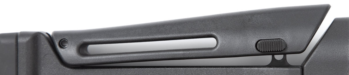
LOCKING STEEL HINGE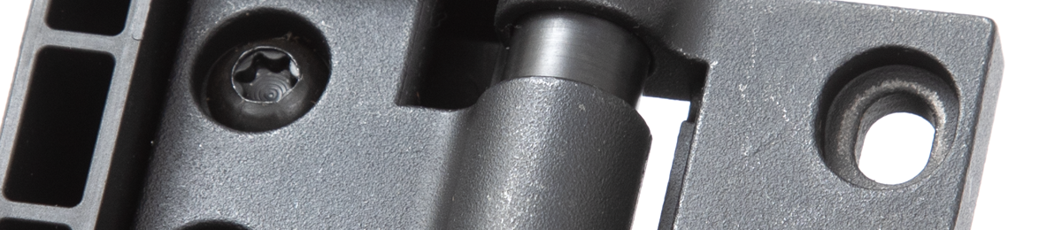
ADJUSTABLE LENGTH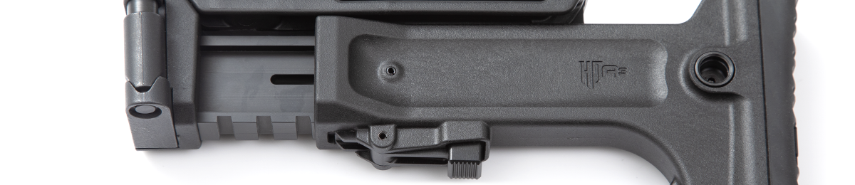
PISTOL BRACE VARIANT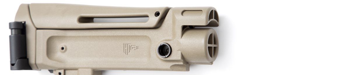
BUILT-IN QD SLING MOUNTS
RUBBER BUTTPAD
OPERATION (VIDEO):
INSTALLATION:
1. Physically and visually check that the firearm is unloaded and that the magazine and ammo have been removed.
2. Remove the factory stock, brace or end cap.
3. Insert the cylindrical part (labeled as part "A" in the diagram below) into the cavity on the back of the firearm. The side with the larger tapered edge should go in first. Line up the hole in part "A" with the threaded hold inside the cavity. 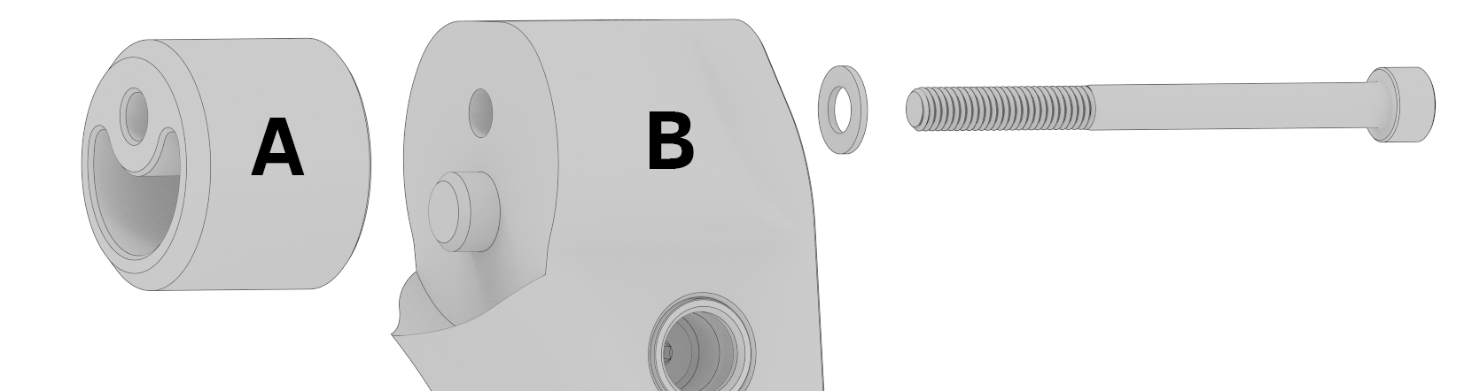
4. Install part "B" onto the firearm. One end will be inserted into the cavity at the bottom of the grip and the other end will fit into the previously placed part "A". With part "B" in place install the included screw and washer then tighten it down with a 4mm hex wrench or bit.
5. Thread in the set screw at the bottom of the grip until it is just past flush with the bottom of the part as shown in the image below. If you go too far it will start to push the part out of the grip. If this happens just back the set screw out a bit. The function of this screw is to keep the part from being able to be pulled out of the grip. There may still be a little in/out play in the part but it won't be able to be removed once the set screw is in place. 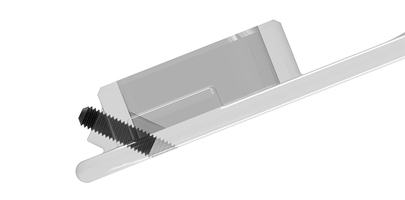
Product Videos
Custom Field
Product Reviews

2 Reviews Hide Reviews Show Reviews
-
HDA3 pistol brace
Very well made product, would definitely buy for another build
-
Worth it.
Decided to go with this stock. I don’t like how the gen2.1 stock goes on my gen2 vector. A little pricey but i like how it looks.


